How to Number Equipments of Electric Power System - Rules and Order
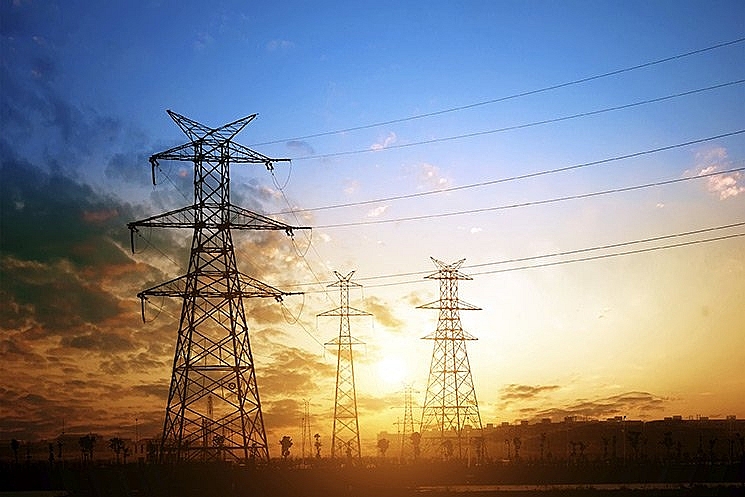 |
| Numbering Equipment in Electric Power System |
What are Equipments of Electric Power System
The electrical power systems range provides advanced technical teaching and training equipment for all elements of a power system including generation, transformation, transmission, distribution, utilisation and protection.
Power transformers, instrument transformers, rotating machines, cables and overhead lines, circuit interrupters (fuses, surge arresters, circuit breakers). Insulating materials used in power equipment, dielectric properties. Electric stress calculation, field grading. Thermal rating of major equipment. Electrodynamic forces in power equipment. Overcurrent, overvoltage, harmonics: causes and effects on equipment operation. High-voltage measurement and testing. Condition monitoring and insulation assessment. Electrical safety: earthing systems for equipment and personnel protection. Utilisation of electrical energy (e.g. lighting and industrial heating).
An electric power system is defined as a network of electrical components used to supply, transfer, and consume electric power. The supply is done through some form of generation (e.g. a power plant), the transfer is done through a transmission (via a transmission line) and distribution system, and the consumption can be through residential applications such as powering the lights or air conditioning in your home, or via industrial applications such as the operation of large motors.
Smaller power systems are also found in industry, hospitals, commercial buildings, and homes. The majority of these systems rely upon three-phase AC power—the standard for large-scale power transmission and distribution across the modern world.
Specialized power systems that do not always rely upon three-phase AC power are found in aircraft, electric rail systems, ocean liners, submarines, and automobiles.
The generation plants produce electrical energy at a low voltage level. We keep the generation voltage at a low level because it has some specific advantages. Low voltage generation creates fewer stresses on the armature of the alternator. Hence at low voltage generation, we can construct a smaller alternator with thinner and lighter insulation.
How to Number in Electric Power System Under The Rules and Order
1. Numbering for voltage level:
– Voltage 500 kV: Take the digit 5
– Voltage 220 kV: Take digit 2
– Voltage 110 kV: Take digit 1
– Voltage 66 kV: Take digit 7
– Voltage 35 kV: Take digit 3
– Voltage 22 kV: Take digit 4
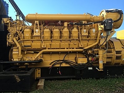 |
| Generator |
– Voltage 15 kV : Take digit 8 (only for generator terminal voltage, synchronous compensator / 15 kV all take number 9)
– Voltage 10 kV: Take number 9 (generator terminal voltage, synchronous compensator / 10 kV all take number 9)
– Voltage 6 kV: Take digit 6 (generator terminal voltage, synchronous compensator < 10 kV all take number 6)
- Other voltage levels are self-determined by the dispatching level with its control authority.
2. Name the busbar:
– The first character is taken as the letter C.
– The second character indicates the voltage level.
– The third character indicates the busbar order, and the number 9 stands for the ring busbar.
Eg:
– C12: indicates busbar 2 voltage 110 kV.
– C21: indicates busbar 1 voltage 220 kV.
– C29: indicates the 220 kV ring busbar.
3. Name of generator or synchronous compensator:
- The first character is specified as follows:
+ For steam thermal power: The symbol is the letter S.
+ For hydroelectricity: The symbol is the letter H.
+ For gas turbines: symbol is GT.
+ For the steam tail of a gas turbine: The symbol is the letter ST.
+ For diesel: The symbol is the letter D.
+ For rotary compensator: The symbol is the letter B.
– The next character is the sequence number of the transmitter.
Eg:
– S1: denotes the number one thermal power generating unit.
– GT2: denotes the second gas turbine unit.
4. Transformer name:
- The first character is specified as follows:
+ For 2 or 3 winding transformers, the symbol is the letter T.
+ For autotransformers, symbol is AT.
+ For self-transformers, the symbol is TD.
+ For generator excitation transformer, symbol is TE.
+ For transformers generating neutral, symbol is TT.
– The next character is the sequence number of the transformer. For self-contained transformers, the next character is the voltage class and sequence number.
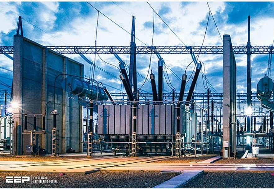 |
| Power transformers are used extensively by traditional electric utility companies, power plants, and industrial plants. |
Eg:
– T1: indicates transformer number one.
– T2: indicates transformer number two.
– TD41: indicates a self-contained transformer with a voltage of 22 kV.
– AT1: indicates autotransformer number one.
5. Name of electric circuit breaker:
– The first character represents the voltage class, as specified in Clause 70 of this Procedure. Particularly for circuit breakers of capacitors, the first character is the letter T, the first character's reactance is the letter K and the second character represents the voltage level.
– The second character (three for reactors and capacitors) represents the position of the circuit breaker, specified as follows:
+ Transformer breaker: Take number 3.
+ Circuit breakers: Take number 7 and number 8 (or number 5 to 8 if the diagram is complicated).
+ Circuit breakers of self-use transformers: Take number 4.
+ Generator pole cutter: Take the number 0.
+ Circuit breaker of rotary compensator: Take zero.
+ Transverse capacitor breaker: Take the number 0.
+ Circuit breakers of vertical compensating capacitors: Take the number 0 (or 9 if the diagram is complicated).
+ Circuit breakers of resistance: Take the number 0 (or 9 if the diagram is complicated).
– The third character (four for reactors and capacitors) represents the sequence number: 1,2,3…
+ For circuit breakers of bypass busbars, the first two characters are followed by: 00.
+ For the circuit breaker between two busbars, the first two characters are followed by the number of the two busbars:
+ For two busbar diagrams (or one busbar with segments), the number of circuit breakers in the even busbar shall be numbered in even order, and the circuit breakers in the odd busbar shall be numbered in odd order.
+ For the polygon diagram numbering the circuit breakers according to the line breakers;
+ For 3/2 (one and a half) diagrams, 4/3 diagrams: depending on the diagram, it can be numbered in the following ways:
• Number the circuit breakers according to the line breakers.
• Number the second character of the breaker in the middle (not connected to the busbar) number 5 or number 6.
• Number the third character in alphabetical order.
Eg:
– 371: indicates circuit breaker 35 kV line number one.
– 131: indicates the circuit breaker of transformer No. 1 voltage level 110 kV.
– 641: indicates the breaker of the self-contained transformer No. 1 with a voltage of 6 kV.
– 903: indicates breaker of generator number three, voltage- 10 kV.
– K504: indicates the circuit breaker of reactor No. 4 of the busbar, voltage 500 kV.
– 100: indicates 110 kV circuit breaker.
– 212: indicates 220 kV busbar contact breaker.
6. Name of resistance:
– The first two characters are the letter KH, the neutral resistance is denoted KT.
– The third character represents the voltage level.
– The 4th character is the number 0.
– The 5th character is the ordinal number of the reacting circuit.
Eg:
– KH504: represents the 500 kV resistance in circuit number four.
– KT303: represents 35 kV neutral resistance connected to transformer 3 neutral.
7. Name of the capacitor:
– The first three characters: For vertical compensating capacitors, take the letters TBD, for horizontal compensating capacitors, take the letters TBN.
– The 4th character represents the voltage level.
– The 5th character is the number 0.
– The 6th character is the serial number of the capacitor connection circuit for vertical compensating capacitors, for horizontal compensating capacitors taken according to the order number of the capacitor.
Eg:
– TBD501: Indicates the 500 kV vertical compensating capacitor in circuit number one.
– TBN302: represents the 35 kV horizontal compensating capacitor in the second circuit.
8. Names of voltage transformers:
– The first character is TU.
-The next characters take the name of the device that the voltage transformer connects to. For devices where the name of the device does not clearly indicate the voltage level, the first two characters will be followed by a character specific to the voltage level, followed by the device name.
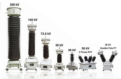 |
| Electromagnetic Voltage Transformers |
Eg:
– TU171: indicates the voltage transformer outside the line 110 kV 171.
– TUC22: indicates the voltage transformer of the busbar number two with a voltage of 220 kV.
– TU5T2: indicates the voltage transformer of the 500 kV T2 transformer.
9. Names of current transformers:
– The first two characters are TI.
– The next characters take the name of the device to which the current transformer is connected. For devices where the name of the device does not clearly indicate the voltage level, the first two characters will be followed by a character specific to the voltage level, followed by the device name.
Eg:
– TI171: indicates a 110 kV current transformer connected to the 171 circuit breaker.
10. Neutral resistor name:
The name of the neutral resistor connected to the neutral point of the transformer or reactance
– The first characters are the letters RT indicating the neutral resistance.
– The next character represents the voltage level.
-. The next character is the name of the device to which the RT is connected.
Eg:
– RT1T1: indicates the neutral resistance connected to the neutral coil 110 kV of transformer T1.
11. Name of lightning protection:
– The first two characters take the letter CS.
– The next character takes the name of the protected device. For devices where the name of the device does not clearly indicate the voltage level, the first two characters will be followed by a character specific to the voltage level, followed by the device name. For lightning arrester, the valve connected to the neutral of the transformer shall be set to zero.
Eg:
– CS1T1: indicates lightning protection of transformer T1 side voltage 110 kV.
– CS0T1: indicates lightning protection connected to the neutral of transformer T1.
– CS271: indicates lightning protection of line 271.
12. Name of isolator:
– The first characters are the name of the circuit breaker or device directly connected to the disconnector (for TU disconnectors, the first characters are the name of the TU, followed by the name of the device directly connected to the switch. isolation), followed by a delimiter (-).
– The next character is specified as follows:
+ The busbar isolator takes the serial number of the busbar connected to the isolator.
+ Line isolator (line-side isolator) take number 7.
+ Isolator connected to transformer take number 3.
+ Isolator connected to the ring busbar with number 9.
+ Isolator short-circuits a device to take the number 0 or number 9.
+ The isolator connects to which segment (which segment's side) it takes the ordinal number of that busbar (or busbar) segment.
+ The name of the disconnector connected to the neutral resistor or the neutral resistance takes the number 0.
Eg:
– 331-3: indicates isolator of transformer T1 with voltage of 35 kV.
– K501-1: indicates the 500 kV resistance disconnector No.1 connected to busbar No. 1.
– TUC22-2: indicates the isolator of the voltage transformer of the busbar No. 2 with 220 kV voltage connected to the No. 2 busbar.
– 171-7: indicates the disconnector outside the 110 kV line of breaker 171.
– 272-9: indicates disconnector of circuit breaker 272 connected to the bypass busbar.
– 275-0: Indicates the disconnector for disconnecting the breaker 275.
– KT301-0: indicates the 35 kV coil neutral switch of transformer T1 connected to the neutral resistance KT301.
13. Fuse name:
– The first characters: For normal fuses, take the letter CC, for self-falling fuses, use the letter FCO.
– The next character is the delimiter (-) and the name of the protected device.
Eg:
– CC-TUC31: indicates the fuse of the busbar voltage transformer C31.
14. Name of earthing switch:
– The first characters are isolators or directly related equipment names.
– The next character for earthing is specified as follows:
+ Grounding of the line and capacitor take number 6.
+ Grounding of transformer, resistance and TU take number 8.
+ The grounding of the circuit breaker takes number 5.
+ The grounding of the busbar takes number 4.
+ Transformer neutral grounding or reactance take number 08.
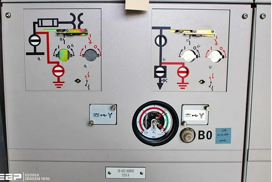 |
| Earthing Switch in Electric Power System |
Eg:
– 271-76: indicates the earthing switch outside the line 271.
– 331-38: indicates the earthing switch of the T1 transformer on the 35 kV side.
– 171-15: indicates the grounding switch of the 171 breaker on the side of the isolator 171-1.
– 131-08: indicates the neutral grounding switch of 110 kV winding of transformer No. 1.
15. Switching devices at branches and middle segments:
– For numbered line segment breakers such as line breakers, numbered transformer down-drop breakers such as transformer circuit breakers.
– For line segment isolators or branch disconnectors, the first characters are numbered as specified in Article 81 (the numbering of disconnectors is performed assuming there is a circuit breaker).
– The last characters are the delimiter (/) and the segment or branch column position.
Eg:
– 371/XX: indicates the breaker of 371 line segments at pole XX, voltage of 35 kV.
– 171-7/XX: indicates 110 kV line segment isolator at column number XX.
– 171-76/XX: indicates the grounding disconnector of the 110 kV line at column number XX.
Why Do We Need An Electrical Power System?From an economic point of view, we always construct a generating station where resources are readily available. Consumers consume electrical energy, but they may stay in such locations where the resources for producing electricity are not available. Not only that, sometimes there are many other constraints due to which we can not construct a generating station nearer to the dense consumer’s localities or load centers. So instead we use an externally located generation source and then transmit this generated power to the load centers through a long transmission line and a distribution system. We call the entire arrangement from generating plants to consumer ends for delivering electricity efficiently and reliably as the electric power system. |

