How to Convert AC to DC: Top Simple Step and Methods
 |
| Illustrated picture. Photo: Mixi's |
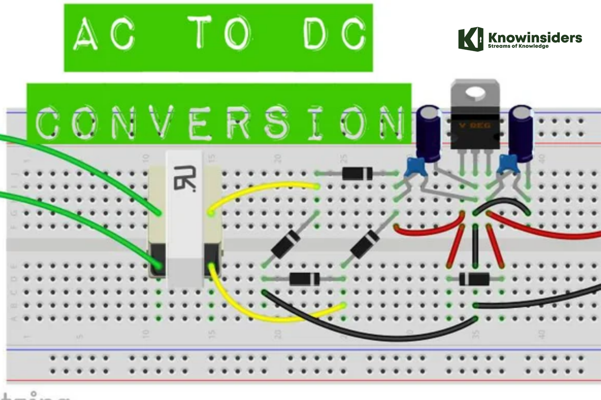
This article explains the main differences between direct and alternating currents. You will also learn how to convert the AC power supply in your home to DC using a small, low-cost bridge rectifier circuit. By converting AC to DC, you can power the DC circuits in your DIY projects.
What is AC Power?
Alternating current (AC) power is the standard electricity format that comes out of outlets. The name comes from the waveform the current takes. To understand the composition of the AC wave, you need to understand that electrical currents come from a flow of electrons. As the electrons in an AC wave move, they can move in a positive direction, which corresponds to the upward part of the sinusoidal wave created by the current. When the electrons have a negative flow, the wave drops down.
These waves come from alternators at electrical power plants creating AC power. Inside an alternator, a wire loop spins inside a magnetic field. The spinning creates the waves of alternating current when the wire moves into areas of different magnetic polarity. For instance, the current changes direction when the wire spins from the north to the south pole areas of the magnetic field. The waves created in the alternator are significant for AC power’s use.
The wave-like motion of AC power gives this electricity form an advantage over DC power. Because it moves in waves, this electricity format can travel farther than DC power. Most outlets in buildings provide AC power. While many electrical devices such as lamps and appliances use AC power, others require converting the electricity into DC format.
What is DC Power?
Direct current (DC) power uses electrons that move in a straight line. This linear movement, in contrast to AC’s wave motion, gives this current its name. This form of current comes from batteries, solar cells, fuel cells, alternators equipped with commutators that create direct energy, and rectifiers that convert from AC to DC power.
Because DC power is so consistent in the voltage delivered, most electronics require this power type. That’s why most electronics have DC power sources in the form of batteries or need to convert AC power from the outlets to DC power through a rectifier. Power supplies often have rectifiers built in along with transformers to raise or lower the voltage to the appropriate level.
Constant voltage for some devices is preferable, such as notebook computers. For such devices, you need an AC-DC power converter if you want to run these electronics from an outlet. The converter transforms the waveform into a steady, straight line. Direct current for electronics is preferable because the highs and lows of alternating current can damage the delicate components inside electronic devices.
How to Convert AC to DC using Diode
What is a Diode?
A Diode is an electronic component that allows electric current to flow in one direction only. It is a semiconductor device that consists of a p-n junction. Diodes one of the most basic semiconductor devices.
Common Application of Diode
Diodes are most commonly used to convert AC to DC, because they pass the positive (+) part of the wave, and block the negative (–) part of the AC signal, or, if they are reversed, they pass only the negative part and not the positive part.
Both p-type and n-type silicon will conduct electricity just like any conductor; however, if a piece of silicon is doped p-type in one section and n-type in an adjacent section, current will flow in only one direction across the junction between the two regions.
Electronic Components needed to Convert AC to DC
Diode = 4 Nos
Step Down Transformer = 1
Capacitor = 1 No
How to Make an AC to DC Converter using Diode
Following are the steps:
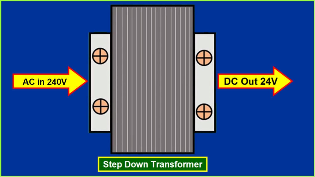
Step 1: Take a Step Down Transformer. If the Input AC is 240 Volt and Required DC Output is 24 Volt, then we need a 240/24 Step Down Transformer.
 |
| Photo: electronicsandyou |
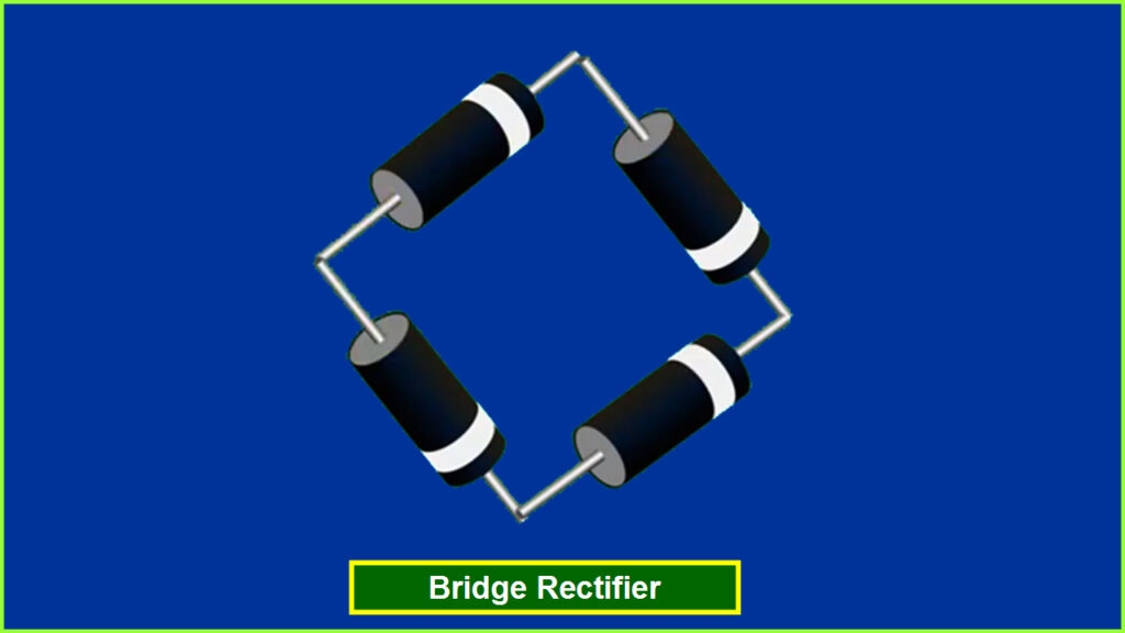
Step 2: Now connect the 4 Diodes in the Following Way – Anode (Positive +) to Cathode (Nagative -). 4 Diodes connected in this format will form a Bridge Rectifier.
 |
| Photo: electronicsandyou |
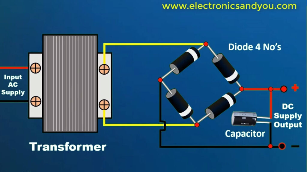
Step 3: Now take a Capacitor and Make connections as per the following diagram.
 |
| Photo: electronicsandyou |
Step 4: Now your AC to DC Converter using Diode is Ready.
Simple Steps to Convert AC to DC: Making the Physical Circuit
1. Stepping down the Voltage Levels
 |
| Photo: Gilson Company, Inc. |
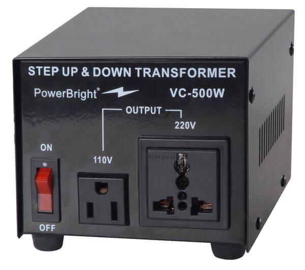
The step-up transformers are used for stepping up the voltage levels and step-down transformers are used for stepping down the voltage levels. Thus, by using a step-down transformer the available 230V AC power supply is converted into 12V AC. The output of this step-down transformer is RMS value and its peak value can be given by the product of the square root of two and RMS value, and is approximately equal to 17V.
There are two windings in the step-down transformers, primary and secondary windings in which primary winding consists of more number of turns compared to the secondary winding (less number of turns). We know that, transformer works based on the principle of Faraday’s laws of electromagnetic induction.
2. AC to DC Power Converter Circuit
 |
| Photo: IMGBIN |
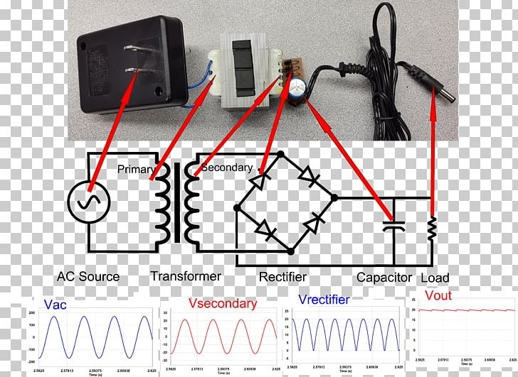
Primarily, the 230V AC power is stepped-down to 12V AC (12V RMS value of which the peak value is 17V approximately), but 5V DC is the required power. So, this stepped-down output 17V AC power has to be converted into DC power and then it is to be stepped down to 5V DC. AC to DC converter namely rectifier is used for converting the 17V AC into DC and there are different types of rectifiers, such as half-wave, full-wave, and bridge rectifiers. Bridge rectifier is mostly preferred compared to the half wave, full wave, and bridge rectifiers.
The rectifier which consists of four diodes and are connected in the form of bridge is called as a bridge rectifier. We know that, the diode conducts only in one direction (during forward bias only), remains in off state in another direction (during reverse bias). Diode generally are uncontrolled i.e., whenever the anode voltage becomes greater than the cathode, then it starts conduction until anode voltage becomes less than the cathode. Hence, diodes are termed as uncontrolled rectifiers.
In the above circuit, during the positive half cycle of the power supply, diodes D2 & D4 conducts and during the negative half cycle of the power supply, diodes D1 & D3 conducts. Thus, the input AC power is rectified into output DC power; but DC output power consists of pulses, hence, it is termed as pulsating DC and is not pure DC. But, due to the internal resistance of the diodes a voltage drop of (2*0.7V) 1.4V occurs and thus, the peak voltage of the rectifier circuit is around 15V (17-1.4).
3. Obtaining Pure DC from Pulsating DC
The 15V DC can be regulated into 5V DC using a step-down converter, but before this, it is required to obtain pure DC power. The pure DC power can be obtained from pulsating DC using filter circuit (L-filter or C-filter or RC-coupled filter can be used to remove the ripples). The C-filter is frequently used for smoothing purposes.
In the circuit, a capacitor is used to store energy while the input voltage is increasing from zero to its peak value and, energy from capacitor can be discharged while the input voltage is decreasing from its peak value to zero. Thus, the pulsating DC can be converted into pure DC using this charging and discharging process of the capacitor.
4. Regulating DC Voltage
The 15V DC output voltage can be regulated using DC voltage regulators such as IC 78XX in which the last two digits XX-represents the output voltage value. Here, let us consider the IC 7805, which is used for maintaining constant 5V DC output even though the input is varying DC voltage (7.2 to 35V DC).
The above figure represents the block diagram of IC7805 DC voltage regulator, it consists of an operating amplifier that acts as an error amplifier, zener diode which used to provide voltage reference, as shown in the below figure.
The series pass element (transistor) is used to dissipate extra energy as heat and heat sink can be used for thermal protection.
Mathematical Conversion
To convert AC to DC, you only need to know the AC value of your source. Using a multimeter, you can measure it.
- Connect the multimeter plugs and set your multimeter on voltage measuring mode by rotating the knob to V~.
- Connect the other end of the probes to the positive and negative terminals of the power source and record the display readings.
Converting DC to AC
Here is the mathematical formula for converting AC to DC:
VDC=VAC/√(2)
For simple calculations, round off the √(2) to 1.4. So, you do not have to use a calculator to divide.
Let's say the measured value was 120V. Add the VAC value you just measured to the formula and calculate it.
VDC = (120/1.4)
VDC = 85.71 Volts
You can use this value to calculate different parameters based on DC voltage. Now, let's move on to making the physical circuit.
| What Is Alternating Current? Alternating Current (AC) is the type of electric current that keeps on changing its magnitude and direction many times a second. The flow of electrons in AC changes at regular intervals. Our homes have an AC supply because, unlike DC, AC voltage travels long distances without much loss of power. What Is Direct Current? With Direct Current, electrons flow in one direction. It is a steady current that doesn't change its direction with time. What Are the Main Differences Between AC and DC? There are two main differences: 1. In DC, the current flow is constant, whereas, in AC, the flow of current is constantly changing. 2. With AC, the voltage doesn't drop over long distances as it does with DC. |
To learn more about AC and DC Power, check out the video now!
For more interesting news of KnowInsdiers, check out right below!
 How to Convert Minutes to Hours: Easy Ways to Change How to Convert Minutes to Hours: Easy Ways to Change |
 How to Convert PDF To Excel: Best Ways to Change How to Convert PDF To Excel: Best Ways to Change |
 How to Convert Word to PowerPoint How to Convert Word to PowerPoint |

